thanks for sharing this great product and for making the design files available. Earth ground the 0 terminal of your switching PS as well. Their website is in Italian, but it can be translatedtoEnglish. Weakest link: Supply large bulk storage caps. Hi. I have also learned to click every possible link when I cant find what I seek. my other amp on same spaker calble pre amp is quit, Hey i would like to buy this PCB but dont know how to. Wow, best guide about building LM3886 amplifier. of the build guide. With a properly designed grounding layout, the amplifiers output will be completely silent when the source is connected and no music is playing. Use thisSingle-Layer Air Coil Calculatorto find out how many turns you need for a particular wire diameter and coil diameter. Sascha. I have seen in many audio amplifier, that the inductor L is wounded on resistor R. why you placed both component separate ? Package is still on ship. Its a great project and I really liked it. The combination of bulk caps should provide low impedance current throughout the frequency band for the load. Heat sinks with a lower saare better at dissipating heat. Thank you very much for your help which I really appreciate. The reason for its popularityis due to itsvery low distortion, minimal external components, and low cost. To minimize inductance, locatethe Zobel network closeto the output pin (pin 4) and keep the traces short. Im a builder, not the editor of this article. The result was good, but not yet satisfactory, While the Zobel network reduces oscillations caused by inductive loads, the Thiele network reducesoscillations caused by capacitive loads, usually due to longspeaker cables. The downside to rotary switches is that the contacts get dirty over time and will need cleaning but all the circuitry is back on the board keeping the signal path short. The cutofffrequency (Fc) of thisfilter can be found with the equation: The equationcan be rearranged to find avalue ofCinfor a particular Fc: Youfound thevalue for Rinwhen youbalanced the input bias currents, so all youneed now is to choose a cutoff frequency. This is amazing. Great project; thank you for sharing.

Audio input cables from the source can pick up stray electromagnetic interference. Like all the other, simple LM3886 or LM3875 gainclones Ive built the soundstage was magnificent, airy and brought detail to the music Ive never realized before with my regular amps & DAC combinations (nothing high end). Bearing in mind most is subjective, though differences between components of different materials do have a definite measurable difference e.g carbon v metal film resistors, silver mica v polyprop capacitors etc. Have a great day Only one thing- why the pcb ordering link wont work anymore?

I used single sided PCB, but tried sticking to your layout as closely as possible and changed some components especially the Mundorfs for something readily available (and a bit cheaper ;) ). sa: The thermal resistance from the heat sink to the ambient air. It explained so much. I am asking for information by email desoto100@wp.pl. http://www.decdun.me.uk/gainclone_psu.html. Below Ill discuss the guidelines I used to design this PCB layout. Buy a bigger case. Im also going to look at CDE 15000uF caps in the PS to see how that changes the sound. Now that weve seenhow to calculate the component values, we can startdesigning the PCB layout and wiring scheme. But I think three wire transformer output should also do just fine. If you put one on the amps output its got to be a huge, well insulated one to withstand the power output from the amp (I think these are called L-pads). Still no sound , IC is still heating. I have built a couple of the Peter Daniels Audiosector Gainclones before. Peak Reverse Repetitive Voltage 600V 1, Maitrikunj Building, Postal Colony, Opp. This is 3u flight case for power amplifier. You use the TF version, why is that? using tiny values as mentioned in some forums, produces nothing noticeable , at least not to my ears. When you connect a powered audio source to your amplifier, magnetic fields fromthe sources transformer and power supply wires can be coupled intothe ground wires of the audio inputcables. The MAX Input voltage for these particular regulators is 35V. Im trying to understand the origin of the mathematical formulas. I assembled the circuit exactly like the one in the guide, with the following changes in the PSU: 24-0-24 250 VA transformer and 4x 10000 uf 50V, having + -32.8 volts dc. I just priced it, mostly through mouser, DIY coils and substituting Erse MPX caps for the Mundorf. So, my Rm will need to be less than 54k for the current atpin 8 to be greater than0.5 mA. If youre interested in building other amplifiers, we also have a tutorial on making a 25 Watt amplifier with the TDA2050, and making 10 Watt stereo and bridged amplifiers with the TDA2003as well. That wayCcstill filtersradio frequencies, but italso acts as a low pass filter that willset the upper limit of the amplifiers bandwidth. V+(L) / GND L = 25v , V-(L)/GND L =-25v In addition to the DC blocking function, Cinand the input resistor (Rin) form ahigh pass RC filter that sets the low endof the amplifiers bandwidth at the non-inverting input: This filters cutoff frequency (also known as the-3db point or corner frequency) is the frequency at which the filter starts to work. I have a question though. I enjoyed every moment of the explanation, Great work and thank you for sharing. Number of Elements per Chip 1 Hi! In a low pass filter, all frequencies abovethe cutoff frequency will be muted.

When I powered it up it sounded different. On the top layer of the PCB, the power supply, output, and Zobel network traces are routedover the power ground plane. Best tutorial youve ever made and one of the best available online. 3.5 times lower is okay, but Imight be able to do even better with a 470F capacitor.

Look for the picture of the circuit board and choose the Open in Editor button. Good luck, The goalwith wiring is to reduce or eliminate electromagneticinterference between high current and low current wires. thank you so much for your posting of the parts list as well as the power supply schematic and values!! I tested it all on a bench top so there was no common metal case joining the components. I drive 8 ohm speakers so I wanted a bit more horsepower. why is c5 a 63 volt cap that is really high is it necessary? What do you think of these changes? With an 18 V transformer, I would get amaximum supply voltage of: 29.6 V is pretty close to the 30.2 V maximum supply voltage needed by my amplifier, but letscalculate exactly how much output power Idget with this transformer. no sound at the ouput. Hi Stan, Im not Scott, but all the Gerber files are available right st the beginning of the article and the PS Gerbers can be found in the yellow bonus box. v+/v- on psu gives 50 v, but grey/grey or black/black is 18vac. I would like to better understand how to set a value for low-frequency cutoff at the feedback loop. This is the voltage theamplifierneeds from the power supply to get thedesired output power. Csnshould havelow ESR and low ESL, with a voltage rating greater than the rail to rail swing of output voltage. So the question is, if and how much would adding fans to near the circuit affect sound quality? income 22k uses 4 x the voltage so gets warmer so important to have close ppm Thank you for your suggestion, Well done for a great article. The negative supply pinneeds itsown set of decoupling capacitors andthe positive supply pins share a separate set of decoupling capacitors. Im not sure what you mean about you has R4 somewhere else on the board since there is No spot to mount it anywhere else on the board. High current grounds are the ground feeds to the power supply decoupling capacitors, the Zobel network, and the speakers. I therefore decreased the value of the decoupling capacitor Cin to 0.4, which should increase the cut-off frequency to about 18 Hz; this produced a noticeable improvement. Rodolfo, hi The traces for the power supply feeds weremade very wide to minimize the resistance and inductance. I think the sound my LM3886 amp produces is much sweeter and softer than my Yamaha. A comparison with the TDA7294 should be interesting. 1996-2022, Amazon.com, Inc. or its affiliates. The power supply and each of the individual components do have a massive influence, especially as there are so few of them. It also prevents radio frequenciespicked up by the speaker wires from getting back into the amplifiers inverting input through the feedback loop. I did build my own enclosure with about $25 in material and I cut back on the high priced input coupling capacitors to another high grade film type. i disconnected everything to check, and giving power just to the psu i have 50volts cc to the v+ v- terminals , on both channels (50 on L and 50 on R). Please have a look at the pics. No Alessandro, thats not what I said if Im reading your response correctly. I was able to successfully and seamlessly order 10 boards. But oneday I accidently connected -ve rail to +ve end of amplifier and vice versa. The power ground and signal ground are the only ground networks on the PCB. Too much clarity is not something people are used to, which can be an issue Thank you very much for the reply. Hi guys i need help. V+(R)/GND= 25v, V-(R)/GND R= -25v. In this post the author writes about Iphone as input signal source with 1 volt lvl. Thank you. Dave, I am not sure but you can try this Forum: https://www.diyaudio.com/forums/chip-amps/234032-my_ref-fremen-edition-build-thread-tutorial.html. (This is where you find air flow holes across the entire top and bottom of enclosure.) So myminimum gain is: So Ill need to set thegain to at least 15.1 Vo/Viif I want 38.2Watts output power into 6 speakers with a 1 V input voltage. I noticed that in the schematic you have a 100nF cap (Csn). For the hum issue, Ill try the suggestions you listed above. The datasheet recommends a 10, 5 Watt resistor in parallel with a 0.7H inductor. John, Thanks a million for the detailed top quality guidance. Trust me, if you build an amp with the LM3886you will not be disappointed. Tech-lobby MagicBox (No Audio) Pre-Amp 0.5 W AV Control Amplifier.for Convert Old Amplifier to tech Amplifier (Silver). The gain of the LM3886 can be set by changing the values ofresistors Ri and Rf1. Then measure theoveralldimensions to make sure the enclosure will fit everything. The medium value decoupling capacitors supply extracurrent for mid-frequency output. thanks in advance for any clarification but the 615pf definitely goes to ground. lower wattage 40W. If there were a way to trade email addresses, I think that I have a few of the amplifier boards in my shack. Yes, you are not Scott, but you do share something in commonkindness! i burned the 2 caps in 2 different times, the 22uF first, then i made a new board and the 1000uF blew. the difference in price is negligible, The board layout has allowed for flexibility which will allow for experimenting with components. It will be the last big step but i need time to save some money. Keep the components for these circuits right up againstthe chips pins so the traces will be short. To un-mute the amplifier, we need to find avalue forRmso that thecurrent allowed to flow out of pin 8 is greater than 0.5 mA. A; >{{}:Q+-Be_ke'D+~+hN(v{~*%G
^b ,PY3V|)_kNJ h. This is an Excel spreadsheet that calculates output power, heat sink size, gain, and other useful parameters: Since this is a rather long article, here are links to the differentsections: You can also check out this video to see a quick overview of the design process. Anyone has any idea on how to be qualified in order to build this amplifier without major mistakes ? I do not care particular brands of capacitors or any other components as long as their specs meet requirements. Im still fumbling when trying my hand at using the EasyEDA software. Hello, Cin after Rin? Your email address will not be published. Second, Im trying to design the amp to go with a pair of Bose Interaudio 4000 speakers, which have a rating of 10-100W and 4-8 ohms. If its not there, then send us a message through our comment form and well make sure you get it: https://www.circuitbasics.com/contact-us/. Sound quality is severely compromised when the SPiKe circuitry is enabled, so to prevent this we need a heat sink with a thermal resistance low enough to dissipate the maximum power dissipated by the LM3886. You can do this in two different ways- Build everything into the original amp housing or build the additional controls into a separate enclosure. The amplifier I built sounds incredibly good. To convert the total power to a transformer VA rating, a general rule of thumb is to multiply itby a factor of 1.5: This is the VArequiredfor each channel, so for a stereo amplifier powered by a single transformer, just double it: Finding a transformer with a VA of 222 will be hard, but youcanround-up to the next closest value and use a 250 VA transformeror larger. The inductors for the Thiele network are wire wound air coretypes, made by wrapping enamel coated wire (magnet wire) around a cylindricalobject. Best RF Amplifier Manufacturer . First I improved the power supply then I added the zobel and thiele network; Withsmaller values of Ci, the bass will be softer and have less punch, butwith larger values of Ci, the bass will be tighter and havemore impact. Csn and Rsn form a Zobel network atthe amplifiers output: The Zobel network is usedto prevent oscillations caused by inductive loads. I would also like to see a follow up post with details on the power supply. Pin Count 2 I would like to ask some questions. Peak Reverse Recovery Time 50ns Also, at the same time provide IC centric decoupling of the supply. signal shunt to ground paralleled 0.2uf silver mica, 1uf teflon, 3uf polypropylene, 30uf polypropylene 100uf bi-polar nichicon 63v and 330uf nichicon b.p Where would i put in a stereo potentiometer for volume control. Many thanks! This is know as a ground loop, and it can createhum in your amplifiers output. These resistors form a voltage divider that determinesthe voltage at the inverting input (pin 9) of the LM3886: Setting thegain too high mightcause distortion. To reduce interference, keep the audio input and signal ground wires away from these parts or run them at 90 angles if separating them isunavoidable. Make sure you havent got fake chips! A typical value for Tambis room temperature (25C). Dont you think that it is not good to have 4 or more coils close to circuitry or it may be disregarded? With the knowledge and the tools available on this site I have built very modified boards. In addition, I wanted to publish a systematic article with instructions on that. Just a heads up from me regarding the build. Anyone?

I want to use PCs intagrated Realtek sound card as signal source. Alessandro Raco on October 27, 2020 at 1:32 pm Its in the later diagrams and theres a 20k in the calculations. You can really feel it. Pls make thesis on power supply too. Rm and Cm create a time constant that slowly decreases the current at the mute pin when power to the amplifier is shutoff, and slowly increases the current when the amp isturned on. The 680 is in fact the smaller-, the 47pF is the bigger one! All of the traces and printing came out very clean and precise, and there were no defectson any of the boards. Click on the top line choice called Fabrication. and then choose PCB fabrication file. Diode Technology Silicon Junction The best dielectric types for audio capacitors in the picofarad range aresilver mica or polystyrene. love the design and want to build the amplifier This will give youa stronger solder joint andbetter electricalconductivity. Fusing both AC line input and power rails are the best but more work and expense. After correct supply connection nothing coming out of the speaker from both amps. Might be a bit expensive to ship, Im guessing $20-25. If that does not fix it, try bypassing the Thiele network . Hi Georg. that had me confused for a while because of the pcb layout and the image. I have a transformer that feeds 22V at 7A..
I get no sound out of the amplifier and its something I cant figure out on my own. Run to 8 ohm speakers :( when I connect a power supply (tried 2 different ones), voltage slowly rises on both the positive and the negative rail on all power supplies on both channels with no signal through the speakers. If you use an ALPS blue velvet pot there a small PCB boards available (Ebay or Amazon) that mount directly onto the pots pins and make wire attachment easier. All metal parts of the amplifier(likethe heat sinks) should be electrically connected to the chassisto provide a path to earth for any mains voltages that could contact them in the event of a fault. Diode Type Silicon Junction Heat sinks for Natural Convection should be exposed to room air flow. Right off the bat, I have a doubt/concern. I needed to have learned many things from reading this article, and building this amp, before I tackled the My_Ref amp. Karim, just to make you aware, the way the rectifiers are arranged on the PS used in this build is probably why the authors called for the fully plastic coated variety rather than the ones that have a metal top & back. Thanks. The 16 V Zener diode (D1) blocks current flowing out of pin 8 until the diodes breakdown voltage (16 V) has been reached. Hello Circuit Basics.

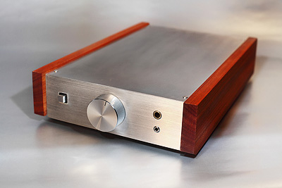
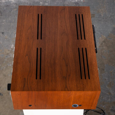
Probably 1 volt too? Okay, thank you. Metal enclosures are the best type because they shield the amplifier from interference caused byfluorescent lights, radios,and cell phones. Is there any order we should follow? The regulation of the transformer Ill be using is 6%. No matching of different drivers resonance frequency etc then crossover to match So you live in the USA David? To each amp board you need to connect one of the V+ PS outputs, then one of the V- PS outputs and one of the PWR GNDs and they all connect on the left side of each amp board to their respective proper connections . based on the typical application of the datasheet, Inductors have a low impedance to low frequency current and a high impedance to high frequency current. The rest of the pairs of GND connections are SPK GND, PWR GND, SIG GND and IN GND. 1-Rb and Rin R4, a 20K resistor, gets soldered directly onto pins 3&9 of the LM3886 chip (there are no holes in the circuit board for R4). There is also a new build-buy forum Mains voltages can vary up to 10% depending on your location. I think I found a misbehaving (though physically intact) decoupling 22uf cap as a suspect and replaced it . But if you still want controls-knobs like I do, then researching in which way a controlscircuit is less likely to decrease/alter the soundquality could be the way to go from here. NASEOH, Chembur Maitrikunj Building Mumbai - 400071, Maharashtra, India, Carry Bags and Multiutility Bags & Pouches, Shop No. The total quiescent power supply current (QPSC) is givenin the LM3886s datasheet as 85 mA. V+(R)/GND= 25v, V-(R)/GND R= -25v. Metal film resistors with a tolerance of 0.1% or less are ideal. Hi. So the maximum thermal resistance (sa) of the heat sink for my amplifier with a Pdmaxof 29.6W is: So Ill need a heat sink rated at less than or equal to 2.1C/W to ensure it candissipate the maximum power produced by the LM3886. This makestheFc: 589 kHz is fairly high, especially since the lowest frequency of AM radio broadcast is535 kHz. this really is the best site for anyone considering building a Gainclone thanks. To separatethelow currentgrounds from the high current grounds, we willcreate several ground networks: These grounds should connect only once at a set of terminals called the main system ground.
Sitemap 30