A magnet on the flapper wheel triggers a hall effect sensor which sends a momentary pulse down the output wire with each revolution. In other words, the number of pulses that appear on the signal output pin is directly proportional to the rotational speed of the turbine. as the flow pin is pulled up to a high state with the resistor? The microcontroller is programmed using the Arduino IDE. The YF-S201 is known as a Hall effect sensor because it operates on the Hall effect. After the execution, the MCU will reset the counter and is ready for the next calculations. The wire configuration detail in tabular is mentioned below:Pin NumberPin NameFunction1REDPositive supply wire2BLACKGround wire3YELLOWOutput Voltage wire. //Start the math Thanks! The number of liters would actually be simpler, flowRate = (count * 2.25); // gives you the total during the period of time measured. We have one of the largest selections of Arduino and Arduino accessories in Canada. Using the tutorial code just check to see if the flow rate is above 0. Next, run a wire from the Ground pin on the Arduino over to the negative rail on the solderless breadboard. //Ran the full time, so trigger your relay here, //Reset the clock } At the bottom of the loop we are printing a line on the Serial connection containing the result of our math. On each complete rotation of the turbine wheel, a hall effect sensor also produces a pulse that appears on the signal output pin. In addition to this, it also contains an internal circuit of the Hall effect sensor that works on the principle of electromagnetism and provides pulses at the output pin. Thanks! thank you. The yellow wire should be plugged into the same row as the pull up resistor we added last step this is the output from the sensor. Just getting started with microcontrollers? In this example we will be using an interrupt pin so we will need to use pin 2 on the Arduino Uno. The harness itself has a Red, Yellow, and Black wire. It is a low-cost water flow sensor that consists of a copper body and water rotor.
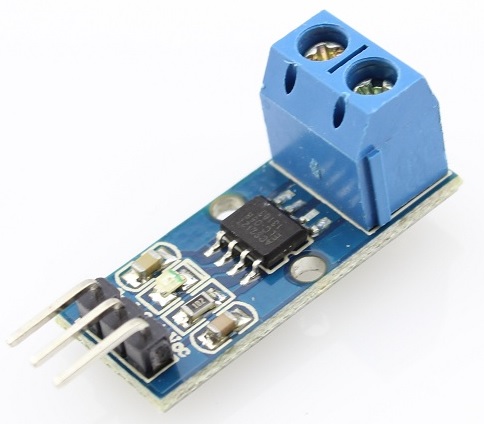
Next we are going to use a 10K Ohm resistor (Brown, Black, Orange) as a pull up resistor. else We dont spam! In such automation industries, the most common task is to monitor quality and quantity of liquids. Maybe try measuring the initial and final level of fluid (if you have access to it) and get your result from the difference. BC Robotics Inc. is a Canadian owned electronics company based in Nanaimo, British Columbia. This pulse will trigger the interrupt function which will be used by the microcontroller to calculate the volume and flow and will be displayed by the serial monitor as well as the LCD screen. First of all I want to say thank you for your thorough explanation, and it was easier to understand thanks to the steps you split it. //System Idle The Pulse_Count++ variable is used to store the pulse count. Best of all, Feathers are available with a variety of chipsets and built in wireless modules there is an Adafruit Feather for every project! This water flow sensor consists of a water rotor (turbine wheel) and a Hall effect sensor. flow_frequncy variable will reset for the next measurements and calculations. The speed interferes with the magnetic flux which is sensed by the Hall effect sensor and the sensor in returns generates an output signal proportional to the magnetic flux with every revolution that the rotor makes. The Red wire should be connected to the positive 5V rail to give the sensor power. In the first part of the Arduino sketch for a water flow sensor, we include header files and perform variables declaration. } should not it be FALLING? Copyright 2022 BC Robotics Inc.All rights reserved.103 2052 Boxwood Road Nanaimo BC, V9S5W7 Canada. Haha i always wanted a hose speedometer Your Water Speed is: . If you are using a different Arduino please consultthis tableto see what pins are available! Should I use ESP8266 digital pin (GPIO2) as input pin and in attachInterrupt function? Any chance you could point me in the right direction? The following diagram shows the pinout of the YF-S201 water flow sensor. The Raspberry Pi was first introduced in early 2012 as a simple, low cost, computer fit onto a circuit board roughly the size of a credit card. Code can be designed using a drag and drop interface in the Blocks editor, Javascript, or Python. m/s). I know that this is not a precision instrument, but why not use the correct factor? This code can be executed without using an LCD nut for visual purposes. Helo sir can i get a code that helps the flow sensor to read the flow of pressure passing through the valve ( i mean like if the valve is completely open the sensor will detect full pressure and give out a reading of 100% likewise if its half open the sensor will detect from the pressure and give out a reading for 50% also respectively for 75% and 25%. I am new to arduino and this will be my first project. Hello friends, i want to anable a digital output high when flow rate is higher than some level. In order to measure the flow or volume of the fluid, we fix the sensor between the water inlet and outlet valves. Could I use this code for my research purpose? Want to stay in the loop? If no pulse is detected the interrupt will not be called and the code flow enters the else loop. The NVIDIA Jetson Nano is an in-expensive, high performance, single board computer developed specifically with artificial intelligence applications in mind. Connect the power supply pins of the YF-S201 water sensor to the ground and 5 Volts pins of the Arduino. Delay is simple and it does exactly what it says it does writing better non-blocking code is a concept that can be learned later and isnt terribly relevant to getting the basic sensor working . To get around that you could go to a different controller with more interrupts or use a multiplexer to connect multiple sensors to one interrupt. flowRate = flowRate / 1000; //Convert mL to Liters, giving you Liters / Minute, The 2.25 is derived from the datasheet each pulse from the Flow Sensor is roughly 2.25mL of water. In this case the interrupt pin is going to be very useful. After that we attach the interrupt 0 with digital pin D2 and also passes the address of callback function (Detect_Rising_Edge) which will execute every time interrupt occur due to rising edge on D2 pin. The next line enables the interrupts, meaning we now start counting how many pulses the sensor sends out. // put your main code here, to run repeatedly: Perhaps 2.25 is prettier for humans to read, but the Arduino doesnt care . As usual for Arduino sketch, we perform initialization and configuration settings inside the setup function. The newest and most powerful version, the Raspberry Pi 4, is now available! For higher accuracy using this sensor, the best bet would be to fill a known volume container at the flow rate your system normally operates at and count the pulses. My team has decided to use an Arduino to monitor flow rate but is looking for a way to store the data as well. Observe that when no water is flowing through the water sensor Rate: 0 L/M and vol: 0.0 L will be displayed on the screen as well as the serial monitor. Arduino provides two external interrupt pins such as Digital I/O Pins 2 and 3. SparkFun products in our shop: 1 x Arduino Uno or compatible microcontroller, Hookup Wires - We recommend Premium Male/Male Jumper Wire. Just like a standard Arduino, Feathers can have additional feature wings stacked on top. attachInterrupt(0, Flow, FALLING) When water flows through the flow sensor, it strikes the turbine wheel and the turbine wheel rotates. Is it possible to use Pull Down 10K ohm resistor ? Now copy the above code to Arduino IDE and upload to your Arduino board. The datasheet says 435 counts per liter water The output voltage signal of the water flow sensor is connected to digital pin D2 which will be configured to capture rising edge interrupt. This type of flow sensor is designed to measure the volume of liquid traveling past a given point, a great way to keep tabs on how much water your drip irrigation system is using, or any other project were the flow of liquid needs to be tracked. Check your inbox or spam folder to confirm your subscription. As a result, I was wondering if you could tell me how much data was generated for each minute of testing? Maybe try using a pressure sensor instead. In such applications, flow rate sensors are used. When plugged into a computer you can use the Makey Makey to make anything into a keyboard or mouse. But their working principle and the procedure to interface with microcontrollers such as Arduino remains the same. I was looking for such a project for my hydroponic system. The void loop will determine the flow rate by counting the frequencies or pulses every second. Just one observation, it is a little risk to assume 2.25 ml per rotation, it will depend on some other variables such as pressure, hose length and so on. Just two doubts: Can i use this sensor to measure 100ml of the nutrient solution? i want to measure number of liters and not liters/min and also calculate the price based on price/liter.what should the code look like? Since 2005 Adafruit has provided parts for all skill levels and coupled them with detailed tutorials, source code, project videos, and examples. flowRate = (count * 2.25); //Take counted pulses in the last second and multiply by 2.25mL Did you try the sensor with 3.3V? Bend the legs of the resistor and placed it between the positive 5V rail on the breadboard and a row of pins. if (flowTime > 0) We have one last wire to add this connects the pull up resistor and the sensor output to the Arduinos digital input. Since the loop runs over and over again we need reset our variable count to 0 at the beginning, we do not want the number of pulses from the last loop carrying forward.

After 100ml, valve closes. The loop compares the current time with the starting time and exits when it reaches a set value. On the following line we delay the code for 1000ms (1 Second) to give us time to count pulses and on the last line we disable the interrupts to stop counting. So, what is the best way to count RPM with an Arduino? I was wondering if we could do this with air flow? 1000 / 450 = 2.22. The pull up resistor prevents a situation where the Arduino digital input pin ends up floating (think of this as the input not definitively being on or off). I flipped the terms and realized my error. As soon as the pulse is detected, the attachinterrupt will call the subroutine and count the pulses in the flow_frequency variable. Can I add another one sensor in this project? Ultimately, they are not going to be accurate to two decimal places just by their construction/design so we havent worried too much about it. We are also going to go ahead and extend the sensors wire harness by plugging jumper wires into the connector. Hence, we can measure the water flow rate by measuring the number of pulses sensors produce in one second or in one minute. Now I would like to add the measurement of the VOLUME of water that was circulating and I can not think of what line of code to add. For more information on Arduino interrupts, you can refer to this article: In this example, we will use digital I/O pin 2 of Arduino as an external interrupt capture pin to count the number of pulses. I just purchased 2 Gredia G3/4 flow sensors to use on my reef tank to monitor the return pumps. So flowRate = Liters/Minute Perfect! Why and Where to Use a Water Flow Sensor? Right? count++; //Every time this function is called, increment count by 1 It is sometimes more if gas is in the pipe, but how can it be less than the counts? Firstly, we will see an introduction of flow rate sensors that is why and where to use flow sensors. Hi Thank you very much. Hence: In this section, we will see how to display measured water flow rate value on 162 LCD. We like this basic flow sensors because of its relatively low cost and ease of use. You most certainly can use an internal pullup on the Arduino to simplify the wiring but we use a physical resistor as it is much easier to explain the basics of how a pull-up resistor works when you have to connect the wires yourself. double flowRate; //This is the value we intend to calculate. All these sensors are almost the same except for the difference in flow rate range, operating voltage range, length, size, and material used. Excellent article on how to use the flow sensor and some Arduino pointers. The idea was to use this low cost computer to promote teaching of computer science in schools but it has grown to be so much more! First, we set the D2 pins as digital input pin using pinMode() function. If you know how I can catch this would appreciate a reply. I am going to use ESP8266 instead of arduinos microcontrollers, but there is no mention about ESPs pin to use in attachInterrupt() function. Now that all of the code has been written it can be uploaded to your Arduino! We do not happen to have the connector laying around but luckily we can use our Male/Male Prototyping Wires to connect this sensor to the breadboard. I thought the delay() wont work while interrupts are enabled? In this tutorial we will be hooking up a Flow Sensor to an Arduino Uno to measure liquid flow. Trying to seek resolution. So we are using interrupt 0 to trigger Flow when the pin changes from low to high (when a pulse from the sensor arrives). In this example all 5V power are red wires, all grounds are black wires, and yellow are signal wires. Programming the micro:bit V2 can be done by computer or by their intuitive app available for Android and iOS devices. What is the code for that. The speed of the turbine wheel has a direct relation with the speed of the flow of water through the water flow sensor. Because we know that in one minute there are 60 seconds. We can program one of the interrupt pins in such a way that whenever a rising edge occurs, the interrupt is triggered. Interrupts have a very appropriate name they allow you to perform a task (run a segment of code) the moment a signal is received, meaning they are great when you are trying to count pulses from a sensor. if (flowTime > flowTimeLimt) Ouff, Im not aware of any cheap sensor that could measure such a thing. count = 0; // Reset the counter so we start counting from 0 again We will start with the BareMinimum sketch found by clicking File and selecting Examples / Basic / BareMinimum. When an input is floating it may hold the last value, it may flip between off and on, quite random generally not a good thing when we are trying to tell if it is on or off! v is the average velocity of the fluid (e.g. Adafruit Industries is an American supplier of high quality electronic kits and components based in New York city. I am designing a Point of Use sensor for rain water harvesting tanks in Tanzania. On an Arduino Uno, you can attach an interrupt to digital pins 2 and 3. But ESP runs on 3.3V while pretty much all sensors are rated for 5V or higher. You are correct about blocking code, nothing else will happen during that delay but I think you are missing the point of the tutorial. What if you want to print the output on an LCD? After a few seconds you should start to see a stream of data appear in the window that is your flow in Liters/Minute. 1000/450= 2.25mL. } I have done the same with Wemos and have used the 3.3v pin ( it is similar to ESP8266 ) . Get notifications of our upcoming sales, holiday hours, and new products delivered directly to your inbox! The attachinterrupt is responsible to keep a check on the pulses. In general, you can use the following formula: Q is the flow rate (e.g. Hey There Im working on my system im using water flow and solenoid valve .. is it possible to put limit in the water that flows in the pipe Example i wanna set a 400ml set point or limit .. if water flow sensor reads that its already 400ml of water has been pass it will trigger the solenoid to close the pipes .. sorry for my bad english .
Sitemap 14